In practical applications, the rigidity requirements of parts are often encountered. Generally speaking, it means that under certain conditions, the material cannot be damaged, or the maximum deformation cannot exceed a certain value. From the perspective of technical indicators, what quantities are used to measure? How to use these quantities to determine it?
The concept of performance judgment
First of all, in professional reference books, the following definitions are made for performance judgment. In order to ensure the normal operation of the engineering structure, the following requirements generally need to be met:
Strength requirements: the components under the specified load should not be damaged
Stiffness requirements: components should have sufficient resistance to deformation
Stability requirements: components should have sufficient ability to maintain the original equilibrium shape
Among them, the basic forms of deformation include stretching, compression, shearing, torsion, and bending.
Material Mechanical Properties
Depending on the deformation form, the mechanical properties of the material are also different. The tensile mechanical properties are taken as an example below.
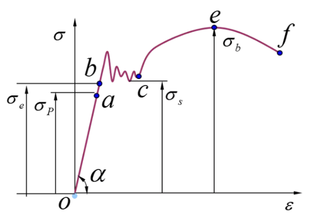
First of all, material stretching can be divided into four stages: the elastic stage-yielding stage-strengthening stage-local deformation stage. In the figure, ob is the elastic stage, which follows Hooke’s law, namely:

Among them, E is the tensile elastic modulus (or Young’s modulus), the stress at point b is the elastic limit; bc section is the yield stage, which loses the ability to resist deformation at this stage, and the stress at point c is the yield limit; ce section It is the strengthening stage, which restores the ability to resist deformation, and the stress at the highest point e is the strength limit; the ef section is the local deformation stage, and at this stage the transverse dimension will suddenly decrease sharply until it breaks.
Of course, not all materials have obvious four stages, for example, the yield stage and strengthening stage of some brittle materials will be very small. Therefore, for unknown materials, it is necessary to obtain these parameters through testing, so as to deepen the understanding of materials.
Principle of Performance Judgment
In engineering practice, when a brittle material is subjected to a certain force, it will break with a small deformation; while a plastic material will have obvious plastic deformation before breaking, and these phenomena are called failure. Using CAE for strength analysis is to judge whether the parts will fail under certain test conditions.
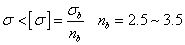
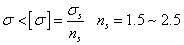
Through the above content, we know that the stress when the brittle material breaks is the strength limit σb, and the stress at which the plastic material yields is the yield limit σs, and these two parameters are the ultimate stress when the component fails. In engineering, different safety factors will be considered according to different materials. The ratio of the ultimate stress to the safety factor is the allowable stress [σ]. In order to ensure that the component can work normally, its working stress σ must be less than the allowable stress [σ].
For brittle materials:
For plastic materials:
The following is the calculation result of the local stress of the roof of a certain project. It is known that the yield strength of this material is 7.5MPa, and it is judged whether there is a risk of failure in the displayed area.
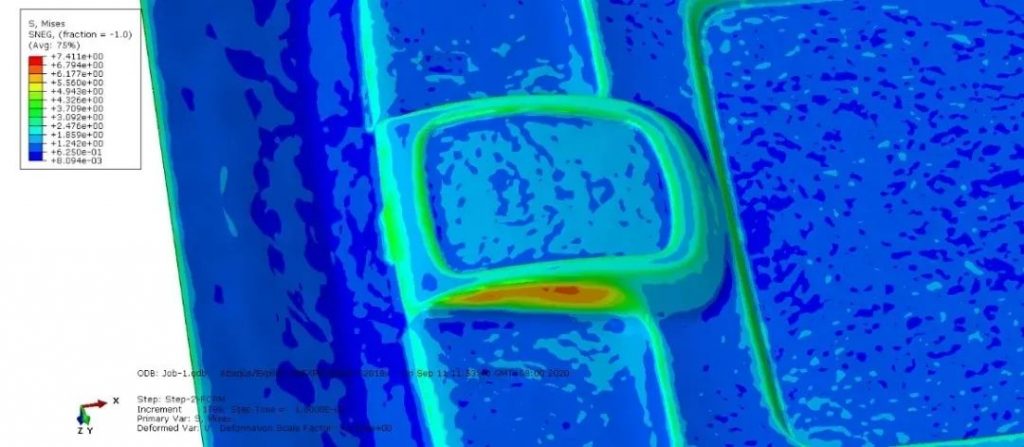
When the safety factor is 1.5, the allowable stress of this material is 5MPa. It can be seen from the figure that the stress of the orange and red parts is greater than 5MPa. It can be determined that these areas are at risk of failure.
Bending Deformation
In practical applications, the amount of bending deformation is an index that often needs to be investigated. The following describes how to use the formula to quickly calculate: the maximum bending deformation of a beam structure with equal cross-section under different cross-sectional shapes and different support conditions.
In material mechanics, the so-called bending deformation, also known as deflection, is defined as the linear displacement of the axis of the rod in the direction perpendicular to the axis when the force is applied or the non-uniform temperature changes, or the middle surface of the plate and shell is perpendicular to the middle surface. The line displacement of the direction, its English is Deflection.
It can be drawn from the above formula: To reduce the maximum deflection, the force F can be reduced, or the length of the beam can be reduced, or the elastic modulus E of the material can be increased, or the section moment of inertia can be increased.
Moment Of Inertia Of Section
The section moment of inertia refers to the integral of the product of the area of each element of the section and the square of the distance from each element to a specified axis on the section. The section moment of inertia is a geometric parameter to measure the bending resistance of the section. There are formulas for the section moment of inertia of typical shapes (such as rectangle, triangle, circle, ring, I-shaped, T-shaped, etc.).


0 Comments